Waste to Water: A twofold clean solution
It is a sad fact that there continues to be an insufficient supply of drinking water in many regions of the world. In some cases, any available water is polluted by industry or agriculture, or not enough surface water or groundwater is available. In both cases, the use of seawater is a possibility for countries near the coast. Before seawater can be used as drinking water, it must first be desalinated, which requires a considerable amount of energy. The waste-to-water concept combines the solutions of two problems and uses the energy from waste incineration to prepare seawater in a seawater desalination plant. This not only provides you with clean, and above all economically-generated drinking water, it also represents a clean and hygienic solution for household and commercial waste.
When planning a waste-to-water plant we first examine the specific local conditions. Depending on the local application, the type and quality of the available waste, and the desired desalination technique, we combine technologies that are common on the market, such as reverse osmosis with membranes (RO), multi-stage flash distillation (MSF) or multi-effect distillation (MED). Membrane methods are used above all when the power generated in the incineration plant can be used for desalination. Distillation methods are suitable when the power generated is to be fed into electricity networks. The distillation method is supplied with waste steam from the turbine here, and is therefore an intelligent way of using waste heat, respectively combined heat and power.
We will draft the most suitable concepts for you and organise the complete implementation, from the initial plans and the preparation of economic feasibility and viability studies to the design, construction and commissioning of the finished turnkey plant.

Waste to Gas: Power, heat and biogas perfectly combined
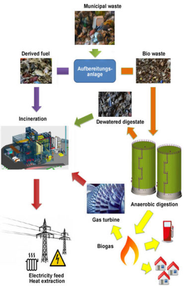
Under the catchword waste-to-gas we combine thermal and biological preparation stages. We interconnect the technology of anaerobic digestion with a waste o energy plant. By combining both recycling techniques, we achieve a high degree of flexibility in extracting energy. Depending on current demand on the market, the proportion of electrical energy, district heating or biogas from the recycling process is increased or reduced.
In our combined system we first separate household waste into organic waste and substitute fuels in a preparation plant. The substitute fuels are sent to waste-to-energy plants and are used there in the thermal recovery process to generate electrical energy, steam, or district heating. After sorting, the organic waste is sent for anaerobic digestion, and is fermented in fermentation tanks to make biogas. A supply network feeds the biogas thus generated to the end consumers in households and filling stations. If demand for biogas sinks, it is made available to the waste-to-energy plant by means of a gas turbine, utilising combined heat and power. Here the biogas also contributes to the generation of electrical energy or district heating. The concept ensures the ideal treatment and recycling of all household waste, while at the same time enabling highly flexible generation of energy. The combination of the three energy types can be adjusted flexibly, for example it is possible to react just as quickly and flexibly to a reduced demand for district heating during warm periods as it is to declining biogas prices.
Rotary kiln: Last stop for hazardous waste
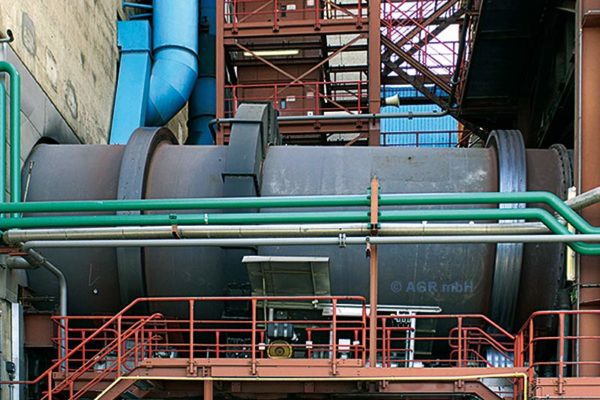
The concept of hazardous waste incineration in a rotary kiln was developed more than 40 years ago and is still an ideal method for incinerating hazardous waste for throughputs of more than 2 t/h. All types of waste and special waste can be treated here, irrespective of contamination, calorific value and consistency. Due to the high incineration temperatures of more than 1,100° C, rotary kilns are mainly used for special waste incineration. At two seconds above this minimum temperature, all organic substances are safely destroyed. Furthermore, incineration provides the possibility to gain energy in the form of steam or electricity from polluted, contaminated and mixed waste.
The concept of classic special waste incineration with a rotary kiln plant involves separate waste storage, feed devices for all types of waste, the rotary kiln, a secondary combustion chamber, a heat recovery steam generator, and flue gas cleaning.
Our rotary kilns are up to twelve metres long, with a diameter of up to five metres. The lining with refractory bricks enables them to be operated at the high temperatures that prevail there. Lengthwise, the rotary kiln is inclined slightly to allow the transport of the waste and slag. Bulky solid materials, barrels and containers, paste-like, liquid and gaseous waste can be incinerated in the rotary kiln. The waste is fed directly in at the front of the rotary kiln either by means of a conventional waste feed chute, an automatic barrel lift for containers, or a lance for gaseous, liquid or paste-like waste. Depending on suitability or calorific value, liquid and gaseous waste can also be fed into the secondary combustion chamber. The high temperatures and rotation of the waste during incineration generate a sintered to vitrified slag in the rotary kiln.
In the secondary combustion chamber, which is downstream from the rotary kiln, full post-combustion of the combustion gases, and thus also residual organics and entrained solid particles, takes place. Suitable liquid waste and gaseous pollutants are introduced at the beginning of the secondary combustion chamber, to ensure that this waste is also burned off completely. The rotary kiln and the secondary combustion chamber form an interrelated system with two-stage combustion, which allows the treatment of special waste with strongly varying consistencies.
Kanadevia Inova Steinmüller plans, constructs and supports turnkey special waste incineration plants. These plants are designed according to individual requirements. We guarantee a highly developed technology that has proven its worth in countless applications. Our thermal treatment uses the energetic potential of the special waste to extract steam, electricity and heat, while at the same time guaranteeing safe and environmentally-friendly disposal.
An alternative for disposing of hazardous waste is gasification and melting with the Direct Melting System (DMS). Talk to us, we will be happy to explain which system presents the best solution for you.
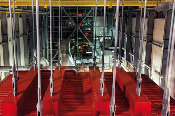
Steam generator – a boiler full of energy
The steam generators by Kanadevia Inova Steinmüller are optimally adapted to each application. When designing them we consider customer requirements and benefit from the many decades of experience of our engineering team, as well as the knowledge gained in countless realised projects.
Calorific value
We optimise the furnace according to the calorific value. We adapt the form and design to allow optimum combustion, while complying with the residence time requirements. We realise concepts from adiabatic combustion chambers to fully cladded versions. When designing the 1st pass we optimise heat transfer by selecting suitable ceramic protective systems, right through to fully cladded versions.
Waste throughput/capacity
We dimension the firing chamber and the subsequent flues and heating surfaces in accordance with the capacity of the firing system and by calculating the optimal flow and temperature profile.
Steam parameters
Whether hot water generator, saturated steam boiler or steam parameters optimised for energy efficiency: We plan the optimal heat transfer, the ideal heating surface arrangement and the best possible energy use for all requirements.
Thermal cycle
The integration of individual energy flows from the water-steam circuit in the steam generator is possible via re-heaters or economiser heating surfaces; we coordinate the interface parameters to ensure that optimisation of the overall plant is in focus.
Corrosion tendency
Depending on the corrosion tendency of the flue gases, the flue gas-side temperature profile, and the surface temperatures of the heating surfaces, we develop the necessary protective systems for you with the right materials to guarantee the long lifetime of the heating surfaces.
Partial load behaviour and plant dynamics
We configure the amount of heating surfaces and dimensions according to the requirements of the plant for the part load behaviour. This allows plant operation with a high degree of flexibility.
Fouling behaviour
When it comes to the flow-related design and the selection of suitable de-dusting methods, we rely on our many years of experience and the analysis of the fouling behaviour of countless plants. We configure and optimise the travel time of the steam generator in accordance with customer requirements. Depending on the design of the heating surfaces, we use spray cleaning, explosion cleaning, soot-blowers, rappers or shot cleaning systems.
Efficiency
With the ideal design of the heating surfaces we achieve the highest possible energetic utilisation of the waste-to-energy plant. The economiser surfaces are also optimally arranged, in order to make maximum use of the heat from the flue gas, while also reduce the exhaust gas temperature.
Steam generator concept
We plan the steam generators according to the available base area and any height restrictions, as well as complying with all necessary framework conditions. It is possible to position the convection passes both vertically and horizontally, and the number and design of the passes are variable. Our steam generators are maintenance-friendly designs that allow time-optimised heating surface exchange.
Static concept
Depending on the size and design of the boiler housing, we realise both suspended and freestanding concepts.
Gas treatment: We make a clean business out of thermal recovery
During the incineration of waste, flue gases containing different kinds of pollutants are produced. If left untreated, they would cause considerable air pollution. We clean flue gases with the latest advanced technologies, formulated on the basis of decades of development and practical experience. Health-damaging emissions based on dioxins, dust or heavy metals, are excluded. The air surrounding the plants is proven to be clean. Thanks to the strict regulations to which thermal waste treatment is subject in Europe, the flue gases from the chimneys of Energy-from-Waste plants are often cleaner than the surrounding air.
Kanadevia Inova Steinmüller offers a broad technology portfolio, from which the optimal solutions can be chosen and combined for every fuel and for all customer-specific framework conditions. Depending on each customer’s wishes, the flue gas cleaning can also be used to improve efficiency, for example by means of a flue gas condensation stage. With decades of experience in constructing flue gas cleaning plants, also in large power stations, we can present corresponding meaningful reference projects from effective and reliable plants. We offer you all technological solutions in terms of gas treatment.
Household waste produces energy
Waste has been a huge problem ever since Antiquity. Mountains of waste and wild landfills dirtied entire settlement areas, introduced diseases, spread epidemics and polluted the groundwater. It was the untreated rubbish heaps in streets and courtyards that facilitated the rapid and fatal spread of the plague in the Middle Ages. Over the centuries, ever increasing quantities of waste were dumped. But only in modern industrial society, with a further exponential growth in garbage, did it become clear that we had created ecological time bombs with such enormous landfills. Even worse: landfills release methane gas, more than twenty times more damaging to the environment than carbon dioxide.
In the European Union the principle of a five-stage waste hierarchy applies, as defined by Directive 2008/98/EC. Waste prevention has the highest priority, followed by re-use. Where waste is unavoidable or cannot be re-used, it should be recycled if possible. Everything that cannot be recycled should be thermally utilised. Only those substance that can no longer be used after thermal recovery should be disposed as landfill.
In Germany, the necessary conclusions were drawn; since June 2005 no more untreated waste is allowed to be dumped in landfills. Laws were similarly changed in many other countries. The understanding of waste treatment has significantly changed in these countries, expressed for example in the willingness of citizens to separate their waste. Nevertheless, large quantities of waste continue to be dumped or openly burned without treatment all over the world. We are faced with the challenge of finding an environmentally-friendly and economically effective solution also for these areas.
Waste prevention
Produce durable goods in order to save raw materials, avoid environmentally-damaging materials in packaging, generally reduce the volume and weight of packaging.
Preparation for re-use
Do not use disposable products, but rather re-usable products.
Recycling
Recycling of previously used goods into other products, e.g. by melting metal
Energetic recovery
Thermal treatment of residual waste to generate useful energy, while complying with efficiency criteria
Was removal/landfill
Thermal waste treatment without complying with efficiency criteria, disposal as landfill

Refuse derived fuels
Highly coveted: Substitute fuels
Refuse derived fuels are secondary fuels that are attained, for example, during the sorting of waste. Among the materials included here are plastics, paper, wood or treated sludge. The concept is defined not by the type of waste, but instead above all by the fact that categorisation and an assessment of the calorific value is made possible by the prior sorting and treatment of the constituents. Whether a product in waste sorting will be recovered materially or thermally depends, among other things, on the quality, severability and degree of contamination. Material recycling often achieves a higher energy efficiency than energetic recovery in some plastics, however the amount of mixed plastics is increasing, particularly in plastic packaging, and individual layers can no longer be separated for recycling. Such plastics are treated to become substitute fuels. To ease handling, the substitute fuels are crushed in shredder plants or die presses or, in the case of paste-like waste, dried and pelleted. Substitute fuels are categorised in special grades using the parameters calorific value, residue on ignition, chlorine content and ash content. The higher the calorific value and the lower the ash content, the more coveted and more expensive the substitute fuel.
As well as being used for co-combustion in waste-to-energy plants, refuse derived fuels are also used in other thermal recovery plants such as cogeneration and cement plants. Some power plants are powered solely by substitute fuels. For the latter, refuse derived fuels with an average calorific value of 12 - 14 MJ/kg are most suitable. In contrast, highly calorific substitute fuels tend to be used for co-combustion in waste incineration plants or cogeneration plants. Refuse derived fuels replace fossil fuels, therefore the market values follow the fluctuations of the market prices for fossil fuels.
Since refuse derived fuels are essentially not different to household waste, the flue gas cleaning requirements are the same as those for a conventional waste incineration plant.
Commercial Waste
Disposed of commercially and recovered safely
Commercial waste, also known as commercial municipal waste fractions, mostly comes from the manufacturing industry or trade, but also from operations in the areas of administration, health, and similar. This waste includes packaging, paper and cardboard, plastics, styrofoam, wood, metal, glass and textiles, and in some cases also building rubble and organic residues. In principle, the composition of commercial waste is similar to that of household waste. Irrespective of the categorisation, commercial waste usually occurs in larger quantities and is delivered by container or truck. The waste generally has a higher calorific value than conventional household waste, and its composition fluctuates strongly.
In most countries, there are special rules and cost models for the disposal of commercial waste. The disposal itself is similar to that of common household waste. In most cases, commercial waste is recycled together with household waste using a waste-to-energy plant, or alternatively special waste incineration plants or DMS systems (Direct Melting System). The energy bound in commercial waste can be made accessible again by means of thermal recovery, and in addition, resources such as metals can be recycled by means of slag treatment. Modern plants for treating commercial and residual waste guarantee the environmentally-friendly, energy-efficient treatment and recovery of waste.
Hazardous waste
Hazardous, corrosive, explosive
When we speak of special waste, we usually mean “hazardous waste”. Under this term the EU waste catalogue lists almost 400 types of waste that are poisonous, explosive, combustible or corrosive, or which contain pathogens. Hazardous waste represents a risk to health and the environment. Specific examples include the special waste of the chemical processing industry, paste-like or liquid production residues, reactive or highly halogenated liquids, waste containing silicon and phosphorus, concentrates, laboratory chemicals, insecticides, pesticides, polychlorinated biphenyls, sewage sludge, hospital waste or severely polluted industrial waste.
When it comes to hazardous waste, proper waste disposal is essential. The substances must not be combusted with normal household waste and belong in plants that can facilitate high-temperature combustion. According to the Best Available Techniques Reference Document (BREF), treatment must follow the three “T”s: Time, Temperature and Turbulence. During the thermal treatment of special waste, temperatures of 1,100 degrees must be attained for at least two seconds in order to avoid emissions that are damaging to health and the environment. Only the high temperature guarantees the safe and certain destruction of all organic substances. Anorganic pollutants such as heavy metals are bound safely into the solid residues, allowing them to be subsequently deposited.
In principle we offer two methods for the treatment of hazardous waste: thermal treatment in a rotary kiln with temperatures around 1,200° C, or gasification in the Direct Melting System (DMS) at 1,800° C. Both methods solve the disposal problem cleanly and safely. Combustion in the rotary kiln and the DMS technique provide the possibility to recover electrical or thermal energy from the hazardous waste. This technology is currently the most suitable method for the safe and economically efficient treatment of large quantities of special waste.
Depending on the type, hazardous waste has different calorific values. One special feature is the higher calorific value in some cases, compared to household waste, and the fact that much of the waste is paste-like or liquid. Paste-like waste is difficult to treat with a grate system; combustion in this case causes increased slag flow, which covers the grate, and also to dripping and ignition beneath the grate. When combusting in a rotary kiln, attention should be given to a careful composition of the waste, due to the different calorific values. The storage and documentation of the waste is also more complicated. In addition, contamination-free zones must be created for clinical waste, and chemicals must be stored safely and separately. We are happy to advise you on the right storage concept, as well as on the application possibilities and the best solution for your requirements.
Our fabric filters: Reliable and highly efficient separators
Our fabric filter technology has proven its worth in many different areas of application and industries. Even in difficult applications, separation rates of over 99.9% are achieved. The spectrum ranges from small and medium filters, for example in industrial applications or waste incineration plants, to large filters with up to 10,000 filter bags in large coal-fired power stations. The solid and effective structure means they can be used in extreme conditions, with low maintenance and at the same time large availability. As well as for pure dust separation, fabric filters can also be used in combination with activated carbon as an entrained flow absorber to remove gaseous pollutants such as mercury or dioxins.
Our fabric filters are comprised of several filter compartments with parallel flow. Individual compartments can be temporarily deactivated without interrupting the operation of the overall plant. The flue gas penetrates the filter bags from outside to inside, while the dust particles are held back. The dust forms a filter cake on the surface of the filter bag, which effectively supports separation. The filter cake is removed from the bags at regular intervals by means of a compressed air pulse. The dust removed is fed via a hopper beneath the compartment to an ash removal system. When selecting the most suitable ash removal system, Steinmüller Babcock Environment relies on its decades of experience and recommends the suitable solution for each individual case. In this way we avoid critical interfaces.
The separation behaviour, cleanability, pressure loss characteristics and lifetime of the filter bags depend on the filter medium used. We know the perfect filter material for every application. We also use our many years of expertise in configuring the inlet flow in the filter compartments. Here, the particular challenge is to distribute the flue gas flow equally among the filter bags, avoiding an upward flow sweeping previously separated dusts with it. The inlet flow via a baffle plate, developed by Steinmüller Babcock Environment, provides the ideal solution for the even distribution of the gas flow, with a very low pressure loss.
- High dust separation rate of up to 99.9 %
- Low clean gas dust content of < 1 mg/Nm3
- Simultaneous gaseous pollutant removal possible
- Treatment of large volume flows
- Fully-automated cleaning of the filter bags online during operation
- Exchange of defective filter bags possible during ongoing operation
- No restrictions in the separation of dust with a high specific electrical dust resistance
- Various possibilities of applications in all areas of industry and energy production
- Individual selection of the filter bag material to the operation conditions
Electrostatic precipitator: high-voltage, diverse and environmentally friendly
The function of dust separation in electrostatic precipitators is based on an electric field that is built up between the high-voltage discharging electrodes and the earthed collecting plates. When flue gas flows through the electrostatic precipitator, the dust particles become electrically charged and are collected at the plates through the effect of the electric field. Fine dust can be removed very successfully from the gas in this manner.
Dry Electrostatic precipitators are mostly built horizontally and can vary in size, depending on their purpose. For dust separation behind a large coal-fired power station, an electrostatic precipitator can reach half the size of a football pitch. Smaller electrostatic precipitators are installed behind biomass-fired boilers in the timber industry or in waste incineration plants. Electrostatic precipitators are also used advantageously in industrial applications where no flue gases from combustion processes need to be treated. In various areas of the steel industry, in sinter cooler systems, in room and converter dedusting and in arc and blast furnaces, electrostatic dust separation also makes sense. In resource recovery processes, for example in cement plants, coal refining plants or chemical and petrochemical plants, electrostatic dedusting plays a valuable role by recycling the precipitated product.
In plants with large quantities of dust we achieve efficient separation rates of well over 99.95%. This means that we achieve a clean gas dust content that is well below 10 mg/Nm3. Values that are noticeably below the common guidelines on emissions protection, and which also recommend the electrostatic separation technology for the future. A particular advantage of the technology is the low pressure loss and thus the low energy requirements of the plant.
The high voltage used in the electrostatic precipitator affects only the solid matter in the flue gas and can be controlled on demand. This drastically reduces energy consumption during off-peak plant operation and when the dust can be easily separated.
The collecting plates, made from profiled steel sheets and up to 16 metres in height, and the discharge electrodes carrying the high voltage, in the form of welded pipe constructions, are robust and unbreakable – malfunctions caused by broken electrodes belong in the past. Cleaning takes place fully automatically by means of a robust tumble hammer system. All bearings of the internal rotating parts are specially protected. Low flue gas flow rates of approx. 1m/s prevent erosion of the electrostatic precipitator internals. The result: more robust, low-wear operation with high availibilities and low maintenance and servicing requirements.
With impressive values, the most modern lignite fired power station in the world, in Neurath (Germany), demonstrates the advantages of electric dedusting. The high-voltage units of the electrostatic separator are designed for a maximum total output of 5,500 kW. Thanks to our intelligent output control, with controlled clean gas dust content, we require only 750 kW of power, thus saving more than 85 % of energy.
- High levels of dust separation of over 99.95%
- Low clean gas dust content of < 10mg/Nm3
- Low pressure loss
- Energy-optimised plant operation, adapted to the clean gas dust content
- Robust and reliable technology
- Operation at high temperatures of up to 450° C
- High volume flows of up to 4.5 million Nm3/h can be achieved
- High availabilities with low maintenance and servicing requirements
- Diverse application areas in all sectors of industry and energy generation
- Reliable electrical charging thanks to unbreakable discharge electrodes
Semidry FGD
Semidry flue gas desulphurisation: low investment costs, optimised plant technology
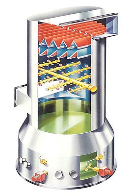
Choosing the right process for a DeSOx plant always depends on the particular case of application. The semidry method is suitable for plants up to 1 million Nm³/h. Here, an aqueous absorbent suspension , usually a calcium hydrate suspension with high reactivity, is injected into the flue gas flow. The acidic pollutant gases react with the absorbent to become salts, while at the same time the water of the lime milk evaporates and the flue gas cools before leaving the absorber. The reaction product is a dry mixture of calcium salts and unreacted lime. The mixture is usually separated in a downstream fabric filter from the flue gas, a partial flow can be recirculated for better efficiencies.
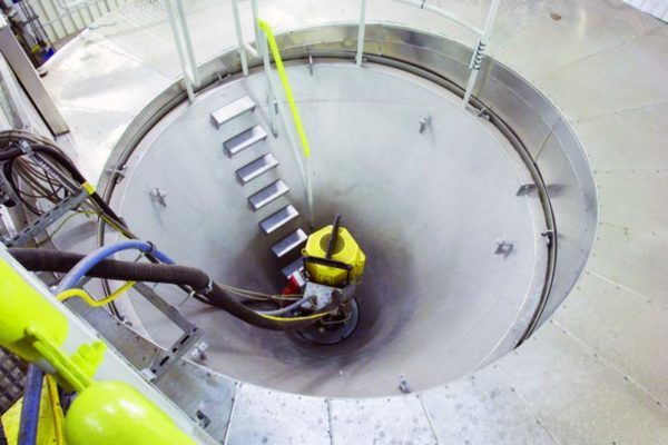
The main design feature of the spray absorber is a cylinder above a conical discharge section. The raw gas distributer is positioned above it, containing the centrally-arranged rotary atomiser. The calcium hydrate suspension is fed to the rotary atomiser. There, an atomised spray with very fine droplets is generated by a rapidly rotating atomiser wheel and distributed evenly into the flue gas flow. The spray absorber is designed to provide a sufficient reaction time between flue gas pollutants and absorbent to bind the SO2 and dry the solid reaction product.
The use of the rotary atomiser as a complete unit, including drive motor, has an economic benefit: In the event of a neccessary maintenance of the atomizer, the complete unit can be replaced in a short time, allowing uninterrupted operations of the boiler plant.
- Use in plants up to approx. 1 million Nm³/h
- Reduced investment costs
- Good utilisation of the absorbent used
- Optimised plant technology
Limestone FGD
Limestone-gypsum desulphurisation: lime scrubbing with an end product
Wet flue gas desulphurisation is usually based on the use of calcareous absorbents (for example limestone, calcium hydrate, quicklime or chalk). Industrially, the use of limestone as an absorbent has prevailed in the area of power stations. The limestone-gypsum method produces gypsum as an end product, which is marketable for industrial re-use. So-called lime scrubbing reliably removes sulphur dioxide, hydrogen chloride, hydrogen fluoride, and ash from the flue gases and is one of the most widely used desulphurisation methods. Kanadevia Inova Steinmüller has 120 reference plants worldwide for this technology, with absorber sizes of up to 3.2 million Nm3/h respectively 1,100 MWel.
The reaction of sulphur dioxide with limestone in the form of suspension is initiated in a spray tower that acts as an absorber. The absorber is divided into three distinct zones, the absorber sump, the contact zone and the absorber head. In the bottom area, the absorber sump, the lime suspension is agitated, supplemented with fresh absorbent, and ventilated. The agitation supports the dissolving of the limestone in the suspension, promotes the even crystallisation of the gypsum, and at the same time prevents the solid material from settling. To oxidise the sulphur dioxide to sulphate (gypsum), finely-distributed oxygen is required. Therefore air is blown into the absorber sump in front of the agitators and distributed or dispersed very finely in the suspension with the agitator flow.
The solid absorbent for the process can either be supplied as powder or ground in a milling unit at the power plant. In the lime milk dosing station the ground limestone is mixed with water before it is injected into the absorber sump.
From the absorber sump some suspension is pumped to the dewatering unit, where the dewatered gypsum is extracted as a marketable product. The surplus water is reused within the limestone/gypsum process.
The flue gas enters the absorber above the sump, and flows upwards through the contact zone. Here are many levels with spray nozzles, which disperse the scrubbing suspension from the sump very finely into the flue gases.
In the contact zone the gaseous sulphur dioxide from the flue gas is dissolved into the scrubbing liquid. After flowing through the contact zone, the flue gas reaches the absorber head and passes through horizontal droplet separators where liquid droplets are removed. When leaving the absorber the cleaned gas is saturated with water vapour has been cooled down to the respective saturation temperature.
- Lowest absorbent costs
- Marketable product (gypsum)
- Best plant availability
- Optimised material and plant concepts
- Worldwide references for all power station sizes and fuels
Economical and effective: SCR denitrification
The SCR (Selective Catalytic Reduction) method is considered to be one of the most economical processes for achieving the NOX removal levels of over 90 % required today. The availability, reliability and efficiency of each plant depend on the solution installed in each case – a task for experts. Kanadevia Inova Steinmüller places the SCR reactor directly downstream the firing (high-dust position) or downstream the flue gas scrubbing (tail-end position). We denitrify with the required operating temperatures of 180-430° C, depending on the type of plant and sulphur load of the flue gas. We have used our technology successfully in steam generators that are fired with coal, oil, biofuels or waste fuels. Other applications, for example after cement furnaces, are in preparation.
When retrofitting existing large steam generators, we adapt the economiser outlet temperature to the required operating temperature of the catalyser with a low load. We have successful references for all possible methods, for example for the modification of an existing economiser, the retrofitting of new eco-bundles downstream from the catalyst, or eco bypasses on the water or gas side.
When Kanadevia Inova Steinmüller retrofits an SCR system, this includes the whole package. We retrofit the entire flue gas routing including the installation of suitable heating surfaces for the regenerative air preheater , the optimisation of the electrostatic precipitator inlet ducting and the new installation or modification of the induced draught fans. Our SCR reactors are flexible and can be equipped with all catalysts on the market, which provides our customers with a clear competitive advantage when it comes to replacing catalyst elements at the end of their lifetime. For even more flexible catalyst management, we may also install reactors with reserve levels upon request. The intelligent layout of the SCR reactors and the catalyser ensures not only the NOX separation and – if required - the destruction of dioxins and furans, but also contributes significantly to mercury removal: Depending on the inlet conditions the catalyst can oxidise more than 90 % of metallic mercury constraints; the oxidised mercury can then be removed in the downstream wet scrubbers. This provides a further decisive advantage, since mercury emission limits are becoming ever more important in Europe.
The expertise of Kanadevia Inova Steinmüller is based on many years of experience and our pioneering role in the field of environmental technology. In 1985 we built Europe’s first commercial high dust SCR plant, and also the world’s first tail-end SCR plant. This long-term experience has allowed valuable findings to flow into the further development of our technology.
In order to continue meeting the high demands for separation efficiencies for different types of fuel, while at the same time ensuring the long life of the catalysts, we optimise our plants with the help of flow models (scale 1:15) and by means of CFD simulation calculations. We achieve ideal homogenisation of both the flue gas velocity and the NOX concentration in the flue gases. Injection and mixing of NH3, NH2OH or UREA into the flue gas is very homogeneous too,thanks to our patented DIVA® mixer. It is a worthwhile investment for several reasons: we achieve high levels of NOx removal, the optimal utilisation of the catalyst activity, and low dust deposits in the flue gas ducts and on the catalyser for high dust applications.
The comprehensive service provided by Kanadevia Inova Steinmüller includes individualised catalyst management. Due to the deposits of certain flue gas components and contact with certain substances, catalyst activity gradually declines over time. At the latest when the maximum permitted NH3 slip has been reached, the activity of the catalyst must be increased. This is possible by means of regeneration, by installing an additional catalyst layer in the reserve level, or by replacing old catalyst layers. We assess the lifespan for you and plan the most economical timeing for stocking up on catalyst volume or replacement. You are always on the safe side with our expertise.